Tolerance defines the acceptable variation in a part’s physical dimensions. It helps specify a part’s critical features and ensures proper assembly.
In practice, specifying exact tolerances for parts can be time-consuming, costly, and inefficient. To improve efficiency, engineers often use standardized tolerance values defined by international standards, such as DIN ISO 2768 and ISO 286.
Powder metallurgy parts can achieve tight tolerances, with the radial dimension of some sintered parts controlled within ±0.01 mm.
Contents
ISO 286
ISO 286, or IT grade, is an international standard that defines a system for tolerances and fits for cylindrical parts.
The table below presents some data for ISO 286 international tolerance grades.
| Nominal Size (mm) | IT5 (μm) | IT6 (μm) | IT7 (μm) | IT8 (μm) | IT9 (μm) | IT10 (μm) | IT11 (μm) | IT12 (μm) |
|---|---|---|---|---|---|---|---|---|
| over 0 up to 3 | 0.3 | 0.5 | 0.8 | 1.2 | 2 | 3 | 4 | 6 |
| over 3 up to 6 | 0.4 | 0.6 | 1 | 1.5 | 2.5 | 4 | 5 | 8 |
| over 6 up to 10 | 0.4 | 0.6 | 1 | 1.5 | 2.5 | 4 | 6 | 9 |
| over 10 up to 18 | 0.5 | 0.8 | 1.2 | 2 | 3 | 5 | 8 | 11 |
| over 18 up to 30 | 0.6 | 1 | 1.5 | 2.5 | 4 | 6 | 9 | 13 |
| over 30 up to 50 | 0.6 | 1 | 1.5 | 2.5 | 4 | 7 | 11 | 16 |
| over 50 up to 80 | 0.8 | 1.2 | 2 | 3 | 5 | 8 | 13 | 19 |
| over 80 up to 120 | 1 | 1.5 | 2.5 | 4 | 6 | 10 | 15 | 22 |
| over 120 up to 180 | 1.2 | 2 | 3.5 | 5 | 8 | 12 | 18 | 25 |
| over 180 up to 250 | 2 | 3 | 4.5 | 7 | 10 | 14 | 20 | 29 |
| over 250 up to 315 | 2.5 | 4 | 6 | 8 | 12 | 16 | 23 | 32 |
| over 315 up to 400 | 3 | 5 | 7 | 9 | 13 | 18 | 25 | 36 |
| over 400 up to 500 | 4 | 6 | 8 | 10 | 15 | 20 | 27 | 40 |
DIN ISO 2768
What is DIN ISO 2768?
DIN ISO 2768 is an international standard that specifies general tolerances for linear dimensions, angular dimensions, form and position tolerances on engineering drawings.
DIN ISO 2768 – 1
DIN ISO 2768 TI specifies Linear and Angular Dimensions, External Radius and Chamfer Heights.
The ISO 2768 standard divides 4 tolerance classes
F: fine tolerance
M: medium tolerance
C: coarse tolerance
V: very coarse tolerance
Linear Dimensions
| Size Range (mm) | f | m | c | v |
|---|---|---|---|---|
| 0.5 up to 3 | ±0.05 | ±0.1 | ±0.2 | – |
| over 3 up to 6 | ±0.05 | ±0.1 | ±0.3 | ±0.5 |
| over 6 up to 30 | ±0.1 | ±0.2 | ±0.5 | ±1.0 |
| over 30 up to 120 | ±0.15 | ±0.3 | ±0.8 | ±1.5 |
| over 120 up to 400 | ±0.2 | ±0.5 | ±1.2 | ±2.5 |
| over 400 up to 1000 | ±0.3 | ±0.8 | ±2.0 | ±4.0 |
| over 1000 up to 2000 | ±0.5 | ±1.2 | ±3.0 | ±6.0 |
| over 2000 up to 4000 | – | ±2.0 | ±4.0 | ±8.0 |
External Radius and Chamfer Heights
| Size Range (mm) | f | m | c | v |
|---|---|---|---|---|
| 0.5 up to 3 | ±0.2 | ±0.2 | ±0.4 | ±0.4 |
| over 3 up to 6 | ±0.5 | ±0.5 | ±1.0 | ±1.0 |
| over 6 | ±1.0 | ±1.0 | ±2.0 | ±2.0 |
Angular Dimensions
| Size Range (º) | f | m | c | v |
|---|---|---|---|---|
| up to 10 | ±1º | ±1º | ±1º30′ | ±3º |
| over 10 up to 50 | ±0º30′ | ±0º30′ | ±1º | ±2º |
| over 50 up to 120 | ±0º20′ | ±0º20′ | ±0º30′ | ±1º |
| over 120 up to 400 | ±0º10′ | ±0º10′ | ±0º15′ | ±0º30′ |
| over 400 | ±0º5′ | ±0º5′ | ±0º10′ | ±0º20′ |
Tolerances of Powder Metallurgy Parts
The size of powder metallurgy parts after pressing is nearly identical to the mold dimensions. After sintering, your PM parts typically expand by 1% to 3%, with radial dimensional accuracy ranging from IT8 to IT9.
After the sizing process, the dimensional accuracy of the sintered parts can improve to IT6-IT7, with small parts achieving tolerances as tight as ±5 μm.
For self-lubricating sintered bushings, the dimensional accuracy of diameters can improve to IT5-IT7.
However, the tolerance for the length or height of sintered metal parts is generally larger, typically around IT12.
Several factors influence the tolerance of powder metallurgy components, including:
- Powder Characteristics
The size, distribution, and uniformity of the powder particles affect the consistency and density of the green compact.
- Compaction Pressure
The amount of pressure applied during compaction affects the part’s density and form, which in turn influences dimensional precision.
- Sintering Process
Temperature, time, and atmosphere during sintering may lead to expansion or shrinkage.
Sizing improves dimensional accuracy by repressing the part to its correct dimensions.
- Tooling and Die Wear
Over time, die and tooling wear down, potentially leading to slight variations in part dimensions.
- Material composition: The material composition of the metal powder and binder can affect the shrinkage and final dimensional stability of your sintered part.
BLUE is ISO 9001:2015 certified and has a professional technical team—your reliable powder metallurgy manufacturer in China.
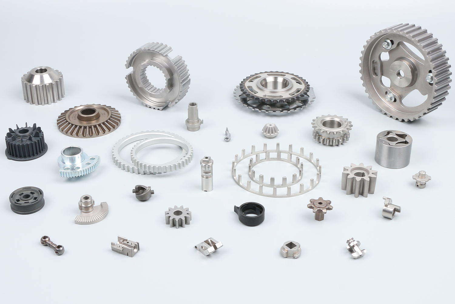
We supply over 100,000 standard parts, including powder metal gears, oil pump rotors & gears, water pump flanges & pulleys, shock absorber components, ABS sensor rings, oil-impregnated bushings, and more, all without tooling fees.
Visit our shop to find exactly what you need for your projects!