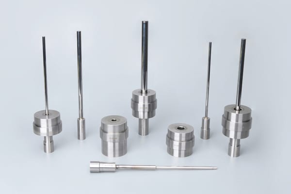
We all know that sintered parts require high precision, which naturally sets demanding standards for powder metallurgy die. Some die achieve dimensional accuracy of up to 5 micrometers.
To produce these high-precision parts, powder metallurgy die design is a top priority. Mold design is a complex task with many factors to consider. Therefore, many parts manufacturers have their own dedicated engineers to design die.

With over 20 years of expertise, BLUE designs and manufactures precision molds for powder metallurgy parts such as oil pump gears, rotors, bushings, flanges, sprockets, and shock absorber components. Our powder metallurgy tooling achieves size tolerances of ±0.002 mm, surface finishes of Ra 0.2–0.4 μm, and positional accuracy within 0.003 mm. We work with premium materials including D2, M2, SKD11, CPM V10, DC53, YG15, and C11 to ensure exceptional die performance. If you choose us as your manufacturer, we also provide free mold design services.
Contents
Powder Metallurgy Molds
Powder metallurgy mold consists of upper punch, lower punch, die, and core rod.
Up Punch and Down Punch
The upper punch applies pressure from the powder compaction press to the metal powder inside the die cavity. It contributes to controlling the shape and size of the finished components.
The lower punch supports the lower part of the compacted powders during compaction process. It helps control the height of the compacted powder in the die cavity.
Before designing the mold, you must determine the number and order of upper and lower punches. You also need to specify the maximum tonnage each punch can handle and its role in forming specific parts.
Die
The die determines the shape and size of finished parts.
During pressing process, the powder in the mold is squeezed by the upper and lower punches and spreads around. Excessive lateral pressure can cause the mold to break. Generally, for iron powder and copper powder, the lateral pressure is 0.5 times the vertical pressure.
Therefore, in order to reduce the lateral pressure, the mold is often divided into two parts: the inner ring and the sleeve ring. The inner ring and the sleeve ring are combined by a tight fit method, which will cause the inner ring to bear compressive stress before pressure is applied. This will neutralize the tensile stresses that occur in the powder under pressure
Core Rod
Some powder metallurgy parts have internal holes, such as round, D-shaped, splined, etc. core rod is used to make the hole.

Dimensions and Tolerances in Powder Metallurgy Die Design
When designing the die size, manufacturers should not only consider the finished product size but also consider:
- Expansion during forming: e
- Shrinkage or expansion during sintering: s
- Reserved correction amount required for sintered parts: d
If the finished product size is D, then the calculation formula for die size is:
Die size = ( D + d ) / (1 – s % ) / ( 1 + e % )
In the mold, the gap between the upper and lower punches, the die, and the core rod (0.01-0.02mm) is too large, powder can easily enter. If it is too small, the gas in the mold cannot escape.
The tolerance of the mold is generally less than 5μm. We can provide powder metallurgy tools with an error within 3μm.
The following table shows the clearance values between the upper punch, lower punch, and the die or core rod.
| Tool size (mm) | Gap (μm) |
| ≤10 | 10 to 15 |
| 10 to 18 | 12 to 18 |
| 18 to 30 | 15 to 22 |
| 30 to 50 | 18 to 27 |
Since the molding machine exerts very high pressure, up to 800 MPa, all relevant factors must be thoroughly considered in die design to prevent cracking.
Powder Metallurgy Tooling Materials
Die materials
The die cavity is usually irregular in shape, and it is easy to crack when the mold is subjected to greater stress. In addition, the die has to withstand the wear of the powders, so the die material should have the following characteristics:
- High strength
- High hardness
- High wear resistance
Common die materials include:
Tool steel, such as D2, SKD11, and M2.
High speed steel: such as CPM10V, VANADIS-60, and ASP-60.
Punches Materials
The material yield strength and hardness of the punches are very high. If the punch undergoes plastic deformation during the pressing process, such as shortening or thickening, it can cause parts to increase in dimension or jam the die.
Moreover, the punch is a dynamic mold, and its toughness and fatigue resistance requirements exceed those of the die. Most punches utilize tool steel, such as A2, SKD11, DRM2. If you need to improve toughness, you can use powder tool steel and high-speed steel, such as ASP-60 (HRC 65 to 69), V-4E (HRC 58 to 64)
Core Rod Materials
The core rod is relatively long and is easy to break during demoulding. So we usually utilize tool steel with high tensile strength, such as SKH9. Normally, we usually use heat treatment process to enhance the hardness of the top of the core rod. If you want to increase wear resistance, we may apply tungsten carbide on the upper part of the core rod and then weld the two parts together with silver solder.
To improve the service life of powder metallurgy molds, manufacturers often use titanium plating to increase the wear resistance of products. However, the cost of titanium plating is relatively high. For example, the cost of titanium plating for ordinary core rods is about $30.

Design of Powder Metallurgical Parts
- Difference in table surface
For parts with large differences in table surfaces, it is necessary to consider designing multiple punches. If one punch is used, the density of the parts will be uneven and it will be difficult to demold.
- Sharp corners
Parts should avoid sharp corners, so upper and lower punches should also be avoided to prevent excessive pressure and collapse. Typically, the width of the tip of the part should be at least 0.1mm.
- Chamfers
The edges of powder metal parts need to be chamfered to avoid burrs. The general chamfer angle is 30° or 45°. R angle is generally not adopted, it will make the punching cost too high.
- Taper
Taper is easy to hit the core rod, so the part must add a small straight section, at least 0.25mm
- Escape hole
If there is no escape hole in the upper punch, the gas will not be able to escape.
- Aspect ratio
The aspect ratio cannot be too large, not more than 3.
- Wall thickness
If the wall thickness of the part is too thin (less than 1.52 mm), or the ratio of length to wall thickness is higher than 8:1, it is easy to cause uneven density and cracking of the part.
FAQ
1. What are the Equipment for Testing Powder Metallurgy Die Accuracy?
Micrometer is ideal for quickly and directly measuring critical dimensions such as the ID, OD, and thickness of a part.
Projector compares part profiles to existing standards and can be employed to quickly assess overall form and dimensional accuracy.

Profiler provides detailed information on surface quality and finish. It help ensure that molds meet specifications for smoothness and dimensional accuracy.
CMM (Coordinate Measuring Machine) provides detailed 3D dimensional data and are ideal for verifying complex geometries and tolerances.
2. What is the Production Cycle of the Mold?
Most molds take 10-15 days to produce. For particularly complex molds or those with high precision, it takes about a month.
3. What Software is Available for Mold Design?
Auto CAD, SolidWorks, and Pro-Engineer.
4. Do Powder Metallurgy Molds Should Backup?
Yes.
Powder Metallurgy Mold production takes a certain amount of time, and when the mold is damaged, it will affect the production rate. If there is a spare mold, production can continue.
5. What is the Lifespan of the Powder Metallurgy Mold?
For molds with simple shapes and structures, such as oil-containing bearings, the mold lifespan is about 300,000 to 500,000 pieces per mold. For more complex shapes, such as oil pump rotors with a diameter of 66 mm, the mold lifespan is about 100,000 pieces per mold.
6. How much does a set of powder metallurgy mold cost?
The mold cost is closely related to its structural complexity, precision, and size. Taking the oil pump rotor with a diameter of 66mm and precision of less than 5μm as an example, a set of molds costs about $4,000.


