


You may already know that powder metallurgy components are near net shape, but they may require secondary machining to meet precise dimensional or functional requirements.
Machining is one of the common secondary operations in powder metallurgy. It removes material using conventional methods such as turning, drilling, milling, or grinding.
This process helps achieve the precise dimensions, surface quality, or features that pressing and sintering alone cannot provide.
Contents
Why Machining Is Needed for Powder Metal Parts?
Tight Tolerances
The radial dimensions of powder metallurgy parts can be controlled with high precision, especially when a sizing process is applied after sintering. Vertical dimensions, on the other hand, are less tightly controlled because of uniaxial compaction and sintering shrinkage. Therefore, to meet higher precision requirements along the vertical axis, operations like grinding or milling are often carried out.
Surface Finish
It is widely recognized that the surface of sintered powder metallurgy parts often contains:
- Porous and rough structures
- Oxide layers
- Slight sintering residues
Therefore, post-processing methods such as turning, milling, grinding, and honing can be used to achieve a smoother surface (e.g., Ra < 0.8 μm). This can help meet sealing, tribological, or aesthetic requirements.
Complex Features
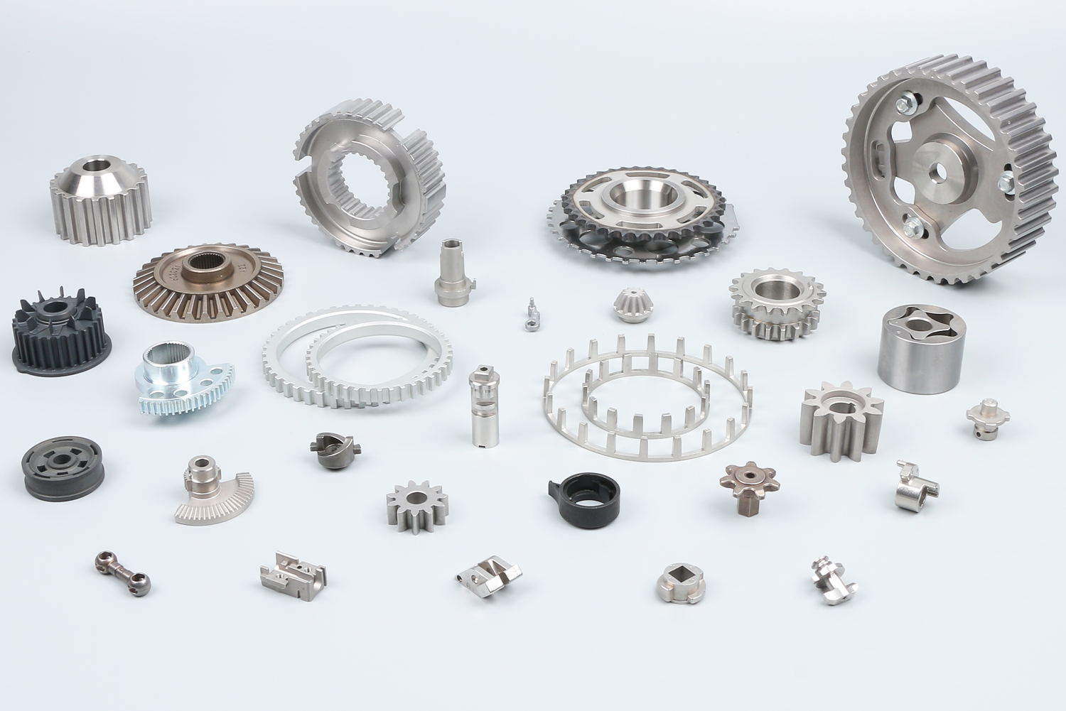
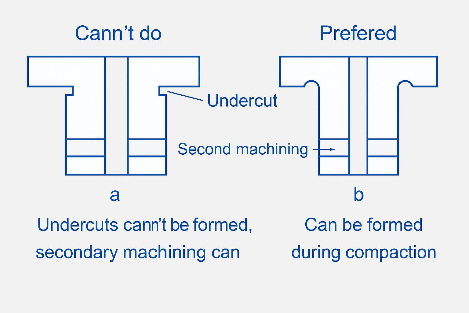
Although powder metallurgy technology can produce complex-shaped parts such as timing pulleys and VVT sprockets, the conventional pressing method is uniaxial. For special or intricate features like cross holes, blind holes, undercut, and threads, powder metallurgy alone cannot form them and requires additional machining.
Common Machining Processes for PM Parts
Turning
Turning shapes the outer surfaces, especially round sections and shoulders. This helps correct size changes after sintering process and improves overall roundness.
Drilling
Powder metallurgy can only form holes aligned with the pressing direction. If the design includes horizontal, angled, or blind holes, these must be machined after sintering by drilling or milling.
Milling
Flat surfaces, slots, and pockets .cannot be directly formed in the mold. That’s where milling comes in. It works well for parts like pump covers or sensor plates, where flatness and clean edges matter. It also prepares joint faces for sealing or fastening.
Grinding
When the part needs a smooth finish or consistent thickness, grinding does the job. It’s often chosen for refining height, surface contact areas, or precision fits. If you’re working with shims or bearing zones, this process probably feels familiar.
Reaming
Pressed holes tend to be slightly undersized or rough. Reaming fine-tunes the diameter and smooths the inner surface. It’s common when the part connects to a shaft, pin, or dowel that must slide in cleanly.
Tapping and Threading
The powder metallurgy pressing process is limited by the mold structure and powder fluidity, and it is usually impossible to directly press threads. So this time you need to use Tapping and Threading
Challenges of Machining Powdered Metal Parts
Due to the inherent porosity and structure formed during the powder metallurgy process, PM components are generally more difficult to machine than cast or forged parts.
Porosity
PM parts retain residual porosity after sintering. During cutting, the tool edge alternates between contacting metal and voids, resulting in discontinuous cutting forces at the microscopic level.
These irregular impacts cause intense micro-vibrations at the tool–workpiece interface. Over time, this leads to cyclic fatigue damage at the cutting edge, particularly at sharp corners and edge radii. The result is micro-chipping or rounding of the edge, which is a common mode of progressive tool wear in PM machining.
Poor Thermal Conductivity
The porous structure of PM materials leads to poor thermal conductivity. The heat generated during cutting cannot be efficiently conducted away, leading to localized heat buildup in the cutting zone. This thermal concentration causes a rapid rise in tool temperature. If the cutting tool lacks sufficient hot hardness or thermal shock resistance, it may undergo thermal softening, cracking, or even localized deformation.
Chemical Reaction and Work Hardening Effects
The elevated temperature during machining promotes surface oxidation of PM materials and may also lead to chemical interactions such as diffusion of carbon from the tool into the workpiece (or vice versa). These reactions increase the surface hardness of the material being cut, accelerating abrasive wear on the tool.
Hardness Variation
During the machining of powder metallurgy materials, the surface layer often shows a significant increase in hardness. Extensive cutting experiments have shown that the typical hardness of iron-based PM materials at room temperature ranges from 24 HRC to 36 HRC. However, localized areas on the machined surface can reach microhardness values exceeding 55 HRC. When this occurs, the cutting edge of the tool experiences severe wear which significantly reduces tool life.
Suggestions for Machining Powder Metallurgy Parts
To reduce tool wear and minimize the impact of frequent tool changes on production efficiency, it is important to select suitable cutting tools and properly adjust machining parameters such as cutting speed, feed rate, and depth of cut.
Tool Materials
PCBN (Polycrystalline Cubic Boron Nitride)
PCBN tools are extremely hard and heat-resistant. They are ideal for cutting iron-based PM parts with hard inclusions or work-hardened zones. PCBN resists edge chipping and performs well under high temperatures and impact loads.
Coated Carbide Tools
Coated carbides combine strong substrates with hard ceramic coatings like TiAlN or TiCN. These tools offer good wear resistance and thermal stability. They are slightly less hard but more cost-effective.
Cutting Parameter Recommendations
The recommended turning speed for powder metallurgy parts is generally between 55 and 120 m/min. For drilling, the cutting speed varies depending on the tool material: 60 m/min for carbide tools and 20 m/min for high-speed steel (HSS) tools.
Process Optimization Strategies
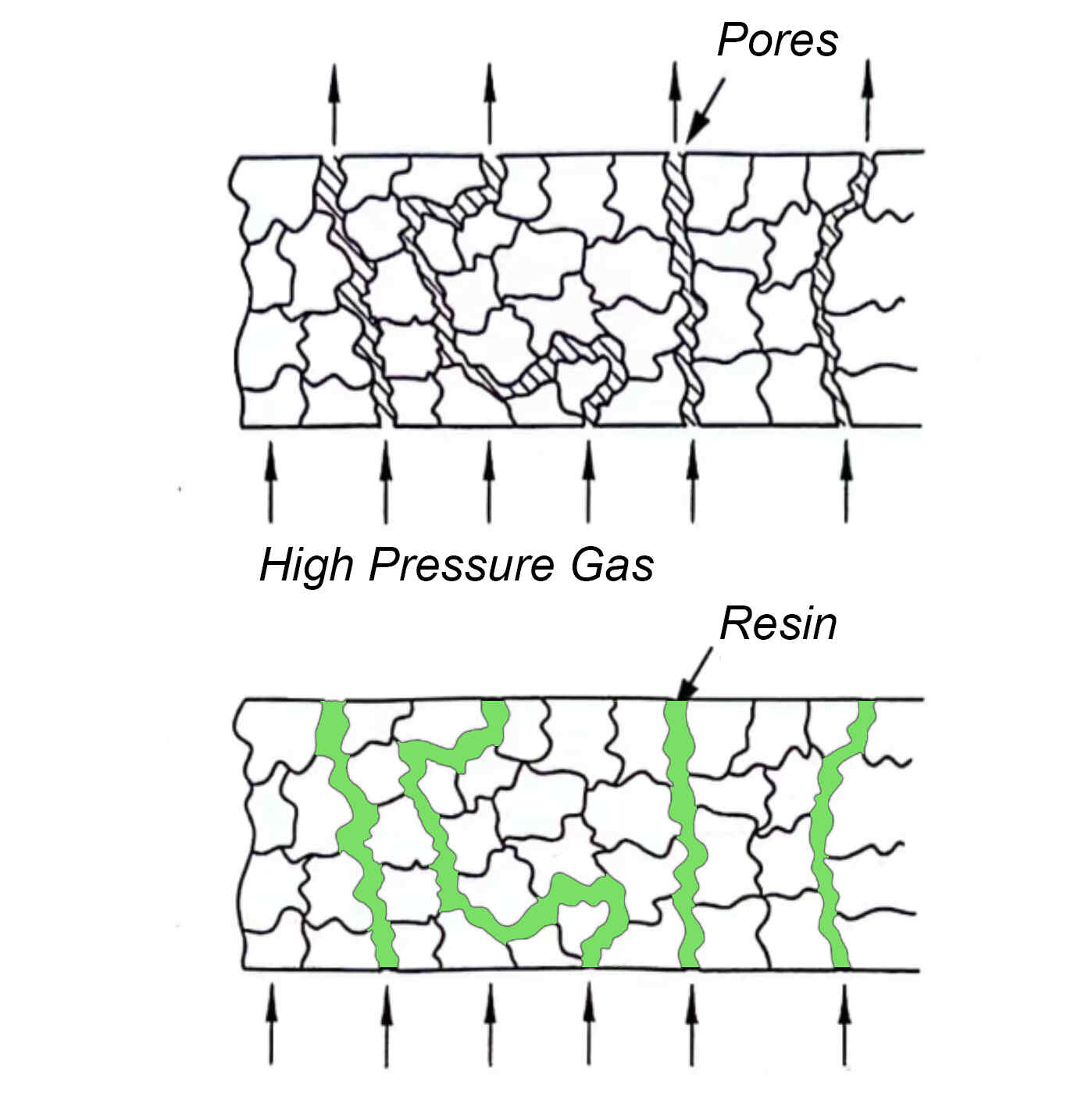
Powder metallurgy parts treated with resin impregnation or copper infiltration can have their internal pores effectively sealed, reducing tool vibration and significantly improving machinability.
In addition, machining can be carried out after presintering and then followed by full sintering. Alternatively, the parts can be machined after sintering and subsequent annealing, which helps reduce hardness and improve machinability.
An effective approach is to incorporate manganese sulfide (MnS) powder into the material. Studies have shown that an addition of 0.5% sulfide yields optimal results. The presence of sulfide acts as a solid lubricant during cutting, effectively improving machinability and reducing tool wear. This method is also applicable to sintered stainless steel parts, where it enhances cutting performance. However, it should be noted that MnS may slightly compromise the corrosion resistance of stainless steels because of the sulfur content in MnS.
BLUE is an ISO 9001:2015 certified PM manufacturer in China, supplying a full range of powder metallurgy parts. We provide standard components with no tooling fees, including structural parts, sintered bushings, MIM parts, and sintered ceramic components.
You can explore our SHOP to compare and select available parts. If you can’t find an exact match, we also provide custom powder metallurgy services.
Contact us today to get started with standard or custom PM parts!