

Successful powder metallurgy (PM) part design begins with understanding process limitations and material properties. You should maintain uniform wall thickness, avoid sharp corners, include proper draft angles, and consider tooling performance. Always balance strength, manufacturability, and cost. A well-designed PM part can save time, reduce defects, and extend tooling life. This powder metallurgy part design guide will help you achieve these goals.
Contents
Design Considerations for Powder Metallurgy
Size Limitation
It’s recommended to keep the aspect ratio within 8:1 for powder metallurgy parts, with diameters not exceeding 250 mm and heights capped at 200 mm.
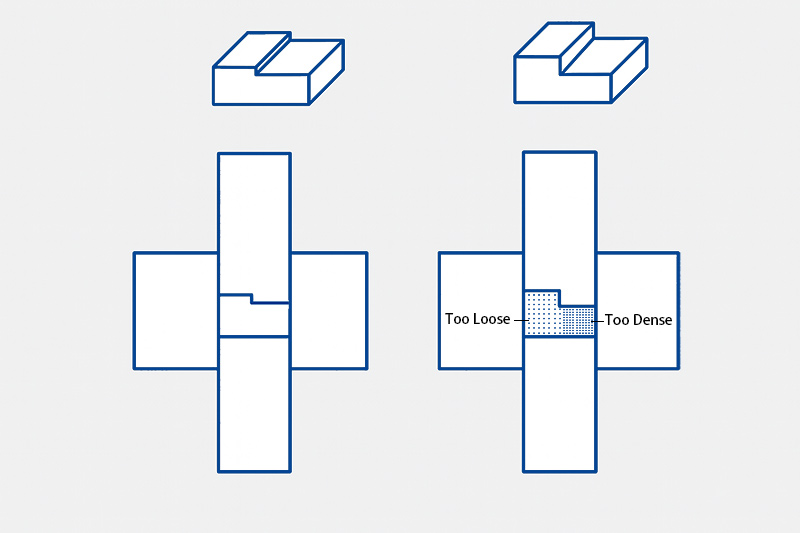
Multi-Level Parts
For two-level or multi-level parts, multiple upper and lower punches, a shelf die, or shelf core rods must be used.
When the height difference between levels is small, stepped upper punches and a single lower punch can be used. For larger height differences, it’s advisable to invert the part and use one upper punch with two lower punches.
Using only a single stepped upper punch for large height differences can cause uneven density and increase the risk of punch breakage or cracking.
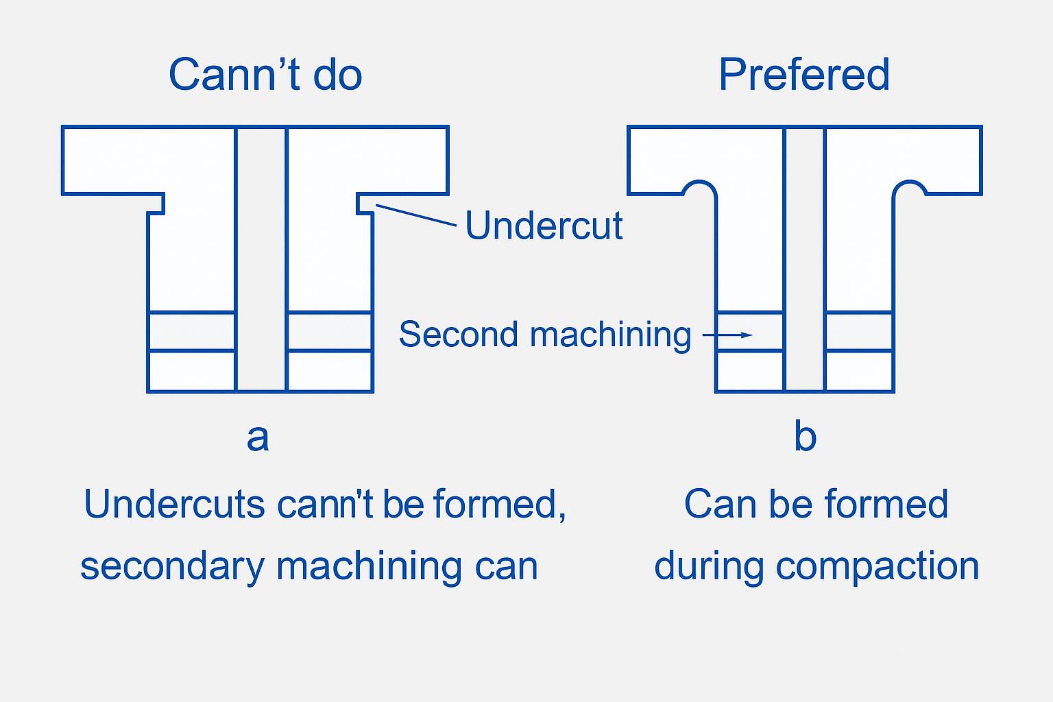
Undercuts
Because powder compaction and ejection both occur along a vertical axis, there can be no obstructions in the press direction. Therefore, features such as undercuts and transverse holes, as shown in Figure a, cannot be formed directly by powder metallurgy pressing and must be produced through secondary machining.
The part shown in Figure b can be directly pressed without additional operations.
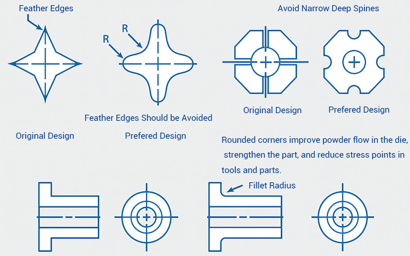
Avoid Sharp Corners
When designing powder metallurgy parts, you should avoid sharp corners to reduce stress concentrations that could cause powder metallurgy die breakage. Likewise, you should not design upper or lower punches with excessively thin or sharp features, as this can lead to punch breakage under high compaction pressure.
Instead, replace sharp corners with flat surfaces, ensuring a minimum width of at least 0.3 mm.
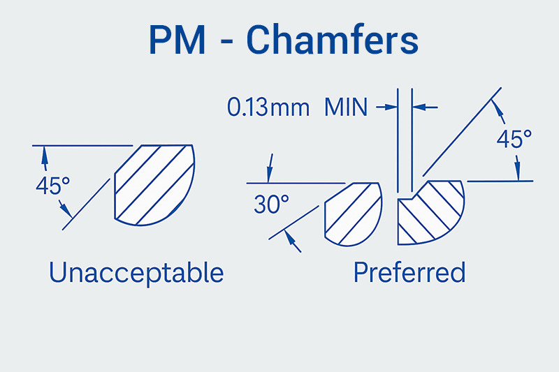
Chamfer
Including radii in your part design can result in burrs during compaction and higher powder metallurgy tooling manufacturing costs. You should avoid radii and instead use chamfers, typically at angles of 30° or 45°.
It is recommended to set a straight section for chamfering with a width of not less than 0.13mm. If the green density is not high, the straight section can be omitted and chamfered directly at 30°.
If you require radiused features, you can achieve them after sintering and before heat treatment through vibratory finishing or machining.
Wall Thickness
When your powder metallurgy part has a length-to-wall-thickness ratio of 8:1 or higher, density variations become unavoidable.
As a general guideline, wall thickness should not be less than 1.52 mm (0.060 inches).
You should avoid designing parts with long, thin walls, as the tooling becomes more fragile and has a shorter service life.
Holes
You can design holes along the pressing direction in various shapes, such as round, D-shaped, splines, and keyways, formed using core rods.
Blind holes, blind steps, and tapered holes are also easily formed in the pressing process.
For large parts, you can incorporate lightening holes to reduce both part weight and the projected pressing area, making the compaction process more efficient.
Taper and Draft
- For straight-through walls, you generally don’t need any draft.
- When designing tapered sections, make sure you add a straight land of at least 0.25 mm between the taper and the die wall or core rod. This helps prevent your upper punch from hitting the taper.
- If you’re adding flange steps, include a small draft to ensure your parts eject smoothly.
- If you’re adding flange steps, bosses, or counterbores made by the punch face, include a small draft on the sidewalls to help your parts eject smoothly and prevent tool sticking or edge chipping.
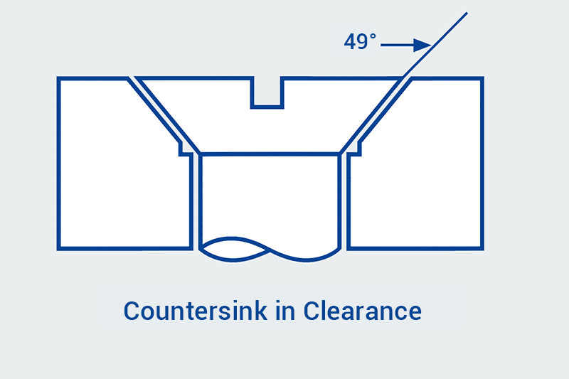
Countersinks
Countersinks add a chamfer around holes for screw or bolt heads. When you form them with a punch in powder metallurgy, include a flat of about 0.25 mm to avoid sharp edges and protect your punch.
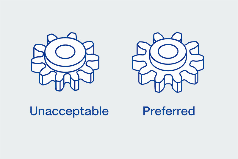
Hub
A hub is the central part of a gear, sprocket, or cam that provides strength and ensures proper alignment on a shaft. In powder metallurgy, you can easily produce hubs, but remember to add a generous fillet between the hub and flange to reduce stress. Also, keep enough material between the hub’s outer diameter and the root diameter of the gear or sprocket to improve strength and manufacturability.
Boss
When forming a boss, place the cavity in the punch. Keep the boss depth to about 85 % or less of the part height and add a minimum 12° draft on each side for smooth ejection. If perpendicular boss walls are required, use a special punch with positive ejection to prevent the compact from sticking.
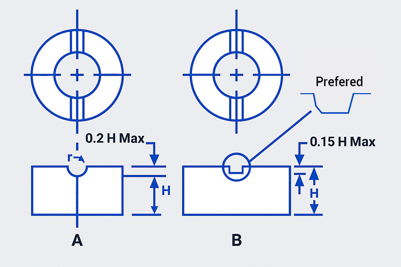
Slots and Grooves
When you press grooves into a part, place the projections on the punch face and stay within these limits so the compact ejects smoothly:
- Curved or semicircular grooves: Keep the depth to about 20 % of the part’s overall length.
- Rectangular grooves: Keep the depth to about 15 % of the part’s length, apply at least 12° draft on walls parallel to the pressing direction, and round every corner.
- you should avoid deep, narrow slots and grooves because they need slender, fragile tooling that can break under high pressure. Powder also doesn’t fill these areas well, causing density variations, dimensional issues, and weaker part performance.
Typical Tolerances for Powder Metallurgy Parts
| Feature | Practical Tolerance (mm) | Possible Tolerance (mm) |
|---|---|---|
| Inside Diameter | ±0.050 | ±0.025 |
| Outside Diameter | ±0.050 | ±0.025 |
| Length (press held) | ±0.013 | ±0.075 |
| Concentricity | ±0.075 | ±0.050 |
| Parallelism of Ends | ±0.038 | ±0.025 |
| Flatness on Ends | ±0.050 | ±0.025 |
Common PM Material Properties
| Material Designation (MPIF 35) | Density (g/cm³) | Tensile Strength (MPa) | Yield Strength (MPa) | Hardness (HRB/HRC) | Typical Applications |
|---|---|---|---|---|---|
| F-0000 (Pure Iron) | 6.5 – 7.0 | 170 – 310 | 130 – 210 | 40 – 70 HRB | Structural parts, magnetic cores |
| FC-0208 (Fe-Cu) | 6.8 – 7.2 | 310 – 480 | 210 – 350 | 60 – 85 HRB | Gears, cams, bearings |
| FC-0205 (Fe-Cu) | 6.8 – 7.2 | 250 – 420 | 170 – 310 | 50 – 80 HRB | Medium strength structural parts |
| FN-0205 (Fe-Ni) | 6.9 – 7.2 | 400 – 620 | 270 – 450 | 80 – 90 HRB | High toughness automotive parts |
| FL-4405 (Fe-0.4%C, Low Alloy) | 6.9 – 7.3 | 480 – 690 | 400 – 600 | 80 – 95 HRB | High-strength parts, automotive gears |
| FLN2-4405 (Fe-Ni-Mo, Low Alloy) | 6.9 – 7.3 | 690 – 860 | 600 – 750 | 25 – 35 HRC | High-load gears, transmission components |
BLUE is a leading supplier of powder metallurgy standard parts in China, with the largest inventory of standard PM parts and no mold fees. We also provide custom PM parts and free mold design services.