
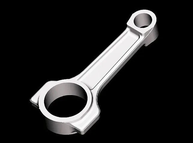
The connecting rod, often called the “con rod,” is a component that plays a critical role as part of the internal combustion engine. This part serves as the crucial link between the piston and the crankshaft and is tasked with converting linear motion into rotational force. In this article, we’ll break down what a connecting rod is, how it works, the various types and materials used, how it’s made, and what happens when it fails.
Contents
Connecting Rod Functions
More than just being the connecting bridge between parts, the connecting rod performs several important functions in the engine.
Force Transmission
During combustion, the piston is forced downward, which generates a force that is transmitted directly to the crankshaft by the connecting rod. This turns the reciprocating motion into torque, thereby acting as a mechanical lever.
Motion Conversion
The connecting rod mainly functions as the means that converts the linear (reciprocating) motion of the piston into the rotating motion of the crankshaft. This means that it permits pivoting on the piston end, and rotation on the shaft end.
Maintains Engine Timing and Balance
Connecting rods also help to maintain synchronized motion and timing between the engine and other components like the camshaft.
Load Management
The connecting rod undergoes both compressive and tensile pressure during combustion. A single stroke can exert tons of force, and the rod must bear this, sometimes for thousands of times per minute.
Types of Connecting Rods
Connecting rods serve the same primary function; however, they come in several different shapes and designs. The various types are suited to specific applications based on certain requirements.
I-Beam Rods
These are the most commonly used rod types in automotive engines. I-beam rods have an “I” shaped cross-section, with a balance between weight and strength. These rods are suited for daily driving and moderate-performance applications. I-beam rods are lightweight, strong, and cost-effective. They are used in passenger cars and light trucks.
H-Beam Rods
These rods have a larger surface area; they are stronger than I-beams, and last longer too. Their “H” cross-section makes them more rigid and capable of handling high-stress environments. H-beam rods are extremely strong and can handle high revolutions per minute (RPM). They are ideal for racing cars and turbocharged engines.
X-beam Rods
A hybrid type of connecting rod consisting of a mix of I-beam and H-beam designs, including their benefits. X-beam rods have a large cross-section; hence, they provide a good balance of high strength, light weight, and are crack-resistant. These rods are suitable for high-performance racing.
Connecting Rod Materials
The choice of material can affect the strength of the connecting rod, the weight, and the cost. To design an engine, the choice of material is based on the type of engine, the intended performance, and load conditions.
Steel Alloys
For designing high-performance engines, forged steel is usually the top choice and the most commonly used material for connecting rods. Steel rods are durable, relatively affordable, and suitable for most automotive applications.
Common Steel Types
Some steel alloy types are ideal materials for manufacturing connecting rods:
- Type 4340, containing chromium, molybdenum, and nickel, is ideal due to its high strength and durability.
- Type 1045, a plain carbon steel, is ideal due to its moderate strength and good wear resistance.
Aluminum Alloys
Aluminum rods are lighter than steel; this helps reduce the overall engine weight and improve responsiveness. However, because they wear out faster, they are ideal for use in high-speed racing engines. Better applied in drag racing and short-duration events.
Titanium Alloys
Titanium rods are known for their high strength-to-weight ratio, and they offer the best of both worlds, but at a premium cost. They are resistant to fatigue, heat, and are ideal for engines that require top-notch performance.
Powder Metallurgy Materials
These powder metallurgy materials are used in some modern engines to ensure consistent quality and reduce machining time. Though they have less tensile strength and fatigue resistance compared to forged steel, they are cost-effective, especially for mass production. Powder metal connecting rods are made by compressing metal powders under high pressure and sintering them. It is ideal for mass-produced engines that require precision and cost control.

Manufacturing Methods
The manufacturing process of a connecting rod greatly determines the performance and reliability of that connecting rod. Each manufacturing method provides different advantages and disadvantages.
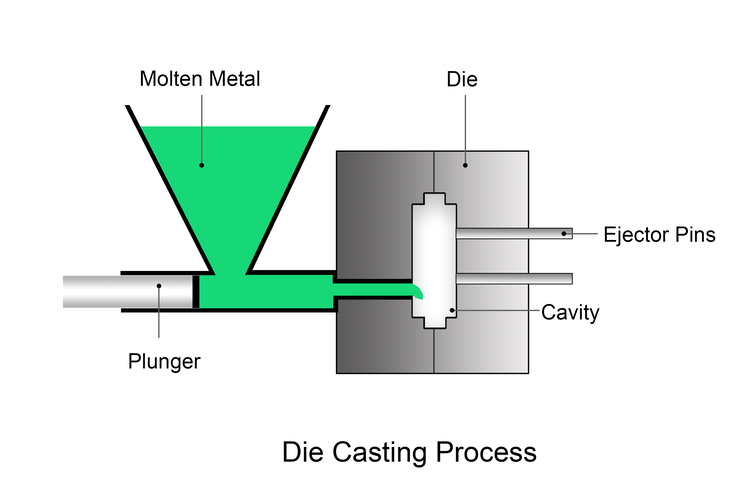
Casting
In the casting method, a molten metal is poured into a mold to create the rod’s shape, then removed after it solidifies. This process begins with creating a pattern in the shape of the desired con rod using a high-precision metal, which is placed in a flask and filled with compacted sand for molding. The molten metal melted in the furnace is poured into the mold at the right temperature for solidification, and when fully formed and cooled, it is removed from the cast.
Final post-processing steps are applied if needed to get the desired connecting rod. This is a low-cost method but generally produces weaker rods due to inconsistent grain flow. This method is suitable for low-stress and economy engines.
Forging
The first step is blanking where the raw material is cut into the desired shape and size of the connecting rod. Subsequently, it is heated at a temperature beyond its recrystallization temperature to ensure malleability for shaping, using medium-frequency induction heating. The malleable blank is passed through rollers for shaping, then placed in a die to compress it into the final shape.
Excess material is trimmed off, holes punched, and the forged conrod is passed through heat treatment to enhance its strength and toughness. Impurities are removed via shot blasting, and final adjustments are made to produce the final connecting rod according to the desired specifications.
Forging is best for manufacturing connecting rods used in high-performance and heavy-duty engines.
Machining (Billet Rods)
This method begins with rough machining where excess material is removed from the forged blank to shape the connecting rod properly. This process includes operations such as boring, drilling, and turning, performed using computer numerical control (CNC) machines. The next step is precision machining which involves boring, honing, grinding, milling, and drilling processes.
These are done to smooth out surfaces, refine the geometry, enhance accuracy, by ensuring that certain features of the connecting rod meet the desired specifications. Heat treatment is applied to enhance its mechanical properties after which final operations take place to remove burrs in preparation for the final assembling. This method allows for extreme customization and precision but it is also expensive. It is suitable for use in high-performance custom engines.
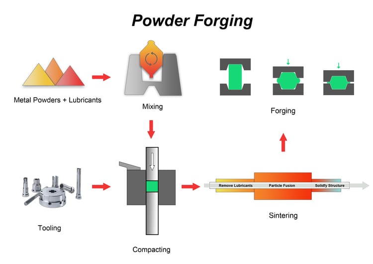
Powder Forging
Powder forging is a manufacturing method that combines conventional powder metallurgy process with forging process to produce high-strength, near-net-shape parts. The process begins with pressing pre-alloyed or diffusion-alloyed metal powder into a compacted preform using a mechanical press. This preform has the basic geometry of the final connecting rod but retains some porosity and limited strength.
The green compact is then sintered in a controlled atmosphere, usually hydrogen or nitrogen-based, at temperatures around 1120 to 1140 degrees Celsius. Sintering bonds the metal particles and gives the preform sufficient integrity for subsequent forging. After sintering, the part is reheated to a forging temperature, typically between 1050 and 1150 degrees Celsius, depending on the alloy used.
At this stage, the sintered preform is hot forged using a mechanical or hydraulic press to achieve near full density and improve mechanical properties. The forging process eliminates residual pores, and improves fatigue resistance by refining the grain structure and generating favorable fiber flow. A forged powder-forged connecting rod offers the advantages of high performance, lightweight design, and low production cost.
Connecting Rods: Common Failure Modes and Causes
Fatigue Failure
Long-term stress cycles can create cracks that grow and lead to rod failure. Common signs include engine knocking and metal debris in the oil.
Bearing Wear
Poor lubrication causes excessive friction, leading to bearing wear or seizure. This may result in low oil pressure and knocking sounds.
Bending or Stretching
Detonation or engine overload can deform the rod, affecting timing and compression. Power loss is a typical symptom.
Cracking
Cracks may develop from manufacturing defects, improper heat treatment, or overheating. Visible cracks and abnormal engine noise are key signs.
BLUE is an ISO 9001:2015 certified powder metallurgy manufacturer with over 20 years of experience. We specialize in powder forged connecting rods for gasoline and diesel engines. We supply standard connecting rods without tooling cost and support custom designs for specific requirements.
FAQ
What Do “Big End” and “Small End” Mean on A Connecting Rod?
- Small End: The top of the rod that connects to the piston pin (gudgeon pin).
- Big End: The bottom of the rod that attaches to the crankshaft journal.
How Do You Maintain or Extend the Life of A Connecting Rod?
- Regular oil changes.
- Using high-quality lubricants according to the manufacturer’s guide.
- Ensuring proper engine tuning (to avoid detonation).
- Regularly check bolts, nuts, and bearings for wear.
What Is the Rod Ratio, and Why Is It Important in Engine Design?
Rod ratio is the ratio between the length of the connecting rod and the stroke of the crankshaft, mathematically expressed as:
Rod Ratio = Rod Length / Stroke.
The rod ratio affects the angulation between the rod and the crankshaft for a given rotation. A higher rod ratio means a reduced angulation, less cylinder wall friction, and better high-RPM performance, and vice versa.