Powder metallurgy (PM) is a great way to produce small and complex parts. However, PM struggles to make miniature parts with fine features, such as thin walls.
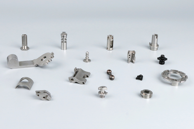
Metal injection molding (MIM) process is a promising technology capable of producing complex parts with diameters as small as 2 mm.
Contents
What is Metal Injection Molding?
Metal injection molding process combines conventional powder metallurgy with plastic injection molding.
Fine metal powder and binders are mixed to create feedstock. The feedstock is then molded by an injection molding machine, followed by debinding and sintering to produce the final product.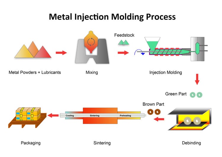
Steps of Metal Injection Molding Process
Compared with plastic material, MIM metal powders are more corrosive. Therefore, the MIM molds are mainly made of tool steel and have wear-resistant coating on the surfaces. Typically, metal injection molding process includes the following steps.
Mixing
The purpose of the mixing process is to get a uniform coating of binder on the surface of the metal particles.
First, the metal powder is placed in the mixer to preheat. Then the binder is added and mixed with the metal powder. The volume ratio of metal powder to binder is about 6:4.
After they are mixed well, you get the injection material-feedstock. The feedstock is extruded like noodles. Then the granulator grinds them into rice-sized pieces before feeding them into the metal injection machine.
If further mixing is required, a high shear mixer is necessary.
The functions of binders in MIM are as follows:
- Improve the fluidity of metal powder
- Give the feedstock a certain adhesion
- Help to form green parts
- Help de-moulding
Injection Molding
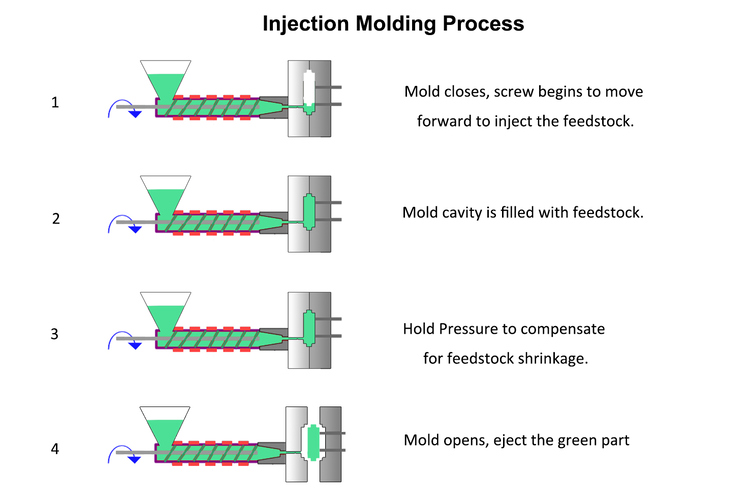
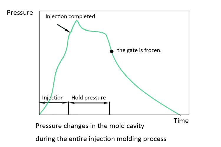
- First, the mold closes and the screw begins to move forward to inject the feedstock.
- The feedstock is heated to about 200°C and fills the entire mold cavity.
- After the injection is completed, you should apply holding pressure to compensate for feedstock shrinkage.
- The gate is frozen, the melt material in the tube cannot enter the mold cavity, and the melt material in the mold cavity continues to cool.
- Then the mold opens and the part is ejected by ejecting the pin.
During injection molding, several factors you should pay attention to.
- Injection speed
An injection speed that is too slow can cause surface defects. An injection speed that is too high to allow air in the cavity to escape through the mold vents can cause voids.
- Switchover point and method
Switchover point is the inflection point from injection to holding pressure. The four commonly used switchover methods are position, hydraulic, time and cavity pressure.
- Holding pressure in injection molding
During injection molding, due to the low temperature inside the mold, the feedstock will shrink a little bit when it cools in the mold. So during the cooling stage, you need to continue to apply pressure and inject a small amount of feedstock to compensate for the shrinkage. This is referred to as holding pressure.
According to 3 ERP, the holding pressure is about 50-65% of the injection pressure.
- Cooling time
Cooling is to allow the part to fully solidify. If the component cools too little, the part may be damaged during the ejection process.
Debinding
Debinding will remove most binders in the green part. This is to prevent defects in the product or affect the mechanical properties of the product during the subsequent sintering process. After debinding, you have a porous, brittle, and low-density part. This is referred to as the “brown part.”
Debinding time is related to the following factors:
- Debinding method
- Part size
- Powder particle size
For example, the same part molded from 20 μm aerosolized copper powder, 10 μm carbonyl iron powder, and 1 μm aluminum oxide powder
They require 3 hours, 6 hours, and 22 hours of solvent debinding time respectively.
1. Thermal Debinding
In the thermal debinding process, you place the green part into a heating furnace to remove the binder. Typically, air, inert gas, or reducing gas is introduced into the heating furnace. What you should pay special attention to is the heating speed. If the binder evaporates too quickly, the part may show defects such as peeling, deformation, blistering, etc.
The advantage of thermal debinding is low cost. The disadvantage is that it takes a long time, which may take 24 hours or more.
2. Solvent Debinding
In order to shorten the debinding time, solvent degreasing came into being. This method is to place the green parts in hexane, heptane or trichloroethylene solvent. The method is that the paraffin and stearic acid in the binders can be dissolved in the solvent. After solvent debinding, thermal degreasing may be required. The purpose is to remove binders that are not dissolved in the solvent, such as polyethylene and polypropylene.
According to “Study of solvent debinding parameters for metal injection moulded 316L stainless steel”, the optimal temperature and time for solvent degreasing of 316L stainless steel are 60℃ and 240 minutes.
The advantages of solvent thermal debinding are shorter degreasing cycle and good product shape retention. The disadvantages are higher cost and solvents may be unfavorable to the environment.
3. Catalytic Debinding
Catalytic debinding uses acidic gases, such as nitric acid, oxalic acid, to decompose some adhesives. Catalytic debinding has excellent product shape retention and fast degreasing rate. However, it is only applicable to adhesives containing polyacetal.
4. Supercritical Fluid Debinding
In supercritical fluid debinding, you use liquid CO2 as a solvent to remove the paraffin at temperatures of about 508–708℃. The process is promising, as it consumes CO2, which is beneficial for the environment.
Compared to solvent and thermal debinding, it has faster debinding rates and fewer part defects. However, the process requires high temperatures and pressures, so it is only suitable for very small parts. Otherwise, large chambers are used, and costs can skyrocket.
MIM Sintering
MIM sintering is similar to conventional powder metallurgy sintering.
Sintering is mainly divided into the following three steps:
- Preheating
Preheating is to further remove binders and initially diffuse and fuse particles.
- Sintering
Brown parts are sintered at a temperature below the melting point. During sintering, the metal particles fuse together, eliminating the pores. Besides, you need to introduce protective gases such as hydrogen, nitrogen, and argon to prevent the product from oxidizing.
- Cooling
The sintered parts are gradually cooled to room temperature. The purpose of cooling is to eliminate the thermal stress during the sintering process. This can avoid cracks in the parts.

Usually, the preheating time is 45 to 60 minutes, the sintering time is about one hour, and the cooling time is about 2 hours.
Unlike powder metallurgy, metal injection molding parts have a larger shrinkage rate during sintering, about 15%-20%. This may require higher sintering temperature and longer sintering time.
The following table shows the sintering temperature and atmosphere of some commonly used metals.
| Materials | Sintering
temperature (℃) |
sintering
atmosphere |
| FN02 | 1180-1290 | Nitrogen |
| FN50 | 1180-1280 | Nitrogen |
|
M2 |
1180-1250 | Nitrogen |
| M4 | 1180-1250 | Nitrogen |
| T15 | 1200-1270 | Nitrogen |
| 17-4 PH | 1200–1360 | Hydrogen |
| 316L | 1250–1380 | Hydrogen |
| 410 | 1250-1375 | Hydrogen |
| 420 | 1200–1340 | Nitrogen |
| 440C | 1200–1280 | Nitrogen |
| 304 | 1250–1375 | Hydrogen |
| W–Cu | 1150–1400 | Hydrogen |
| Pure Cu | 950–1050 | Hydrogen |
| Bronze | 850–1000 | Hydrogen |
| Titanium | 1130–1220 | Argon/ Vacuum |
| Ti-6Al-4V | 1140–1250 | Argon/ Vacuum |
| Inconel 718 | 1200–1280 | Vacuum |
Secondary Processes
After sintering, the MIM parts may need secondary processing according to the needs, such as machining, heat treatment and surface finishing.
MIM Materials
Metal injection molding materials include metal and binders.
MIM Binders
- Wax-based binders
It is made of polyethylene and polypropylene as skeleton binders, and its amount is 30wt%. The balance is paraffin and a small amount of lubricant and activator.
- Water-based binders
Water-based binders are mainly composed of water and polymer materials. Its toxicity is relatively small, so it is more environmentally friendly, but the debinding and drying time is long.
- Solvent-based binders
It has a short drying time and is easy to shape, but the toxicity is higher.
The following table shows some metal binders used in metal injection molding.
| Metal | Binder |
| 316L stainless steel |
l 30% paraffin wax 10% carnauba wax, l 10% bees wax, l 45% polypropylene l 5% stearic acid |
| 17-4 PH stainless steel |
l 64% paraffin wax, l 16% microcrystalline paraffin wax, l 15% ethylene vinyl acetate, l 5% high-density polyethylene |
|
Copper |
l 65% paraffin wax l 30% polyethylene l 5% stearic acid |
| Iron–nickel alloy |
l 79% paraffin wax l 20% ethylene vinyl acetate l 1% stearic acid |
| W–Cu alloy |
l 35% polypropylene l 60% paraffin wax l 5% stearic acid |
MIM Metal
- Stainless Steel: 17-4, 316L, 420, 440C, 310
- Tool Steel: M2, M4, T15, S7, M42
- Titanium: Ti, Ti-6AI-4V, Ti-6Al-7Nb
- Magnetic: Fe49Co2V, Fe50Ni, Fe3Si
- Nickel: Inconel 625, Inconel 718
- Tungsten
- Copper
- Aluminium
MIM Machine
The metal injection molding process requires powder mixing equipment, injection molding machines and sintering furnaces.
Mixer
Common high shear mixers include:
- shear roller
- single screw extruder
- twin screw extruder
- twin cam
- double planetary
- Z-blade mixtures
Twin screw extruder is most favored by their high shear rate and short dwell time.
Metal Injection Molding Machine
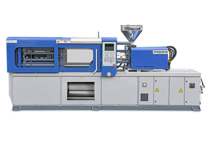
Metal injection molding machine consists of injection unit, clamping unit and hydraulic unit.
Injection unit is responsible for feeding the feedstock into the mold. Clamping unit is responsible for forming and ejecting the green part. Hydraulic unit provides power.
Sintering furnace
Conventional powder metallurgy sintering furnaces are also suitable for MIM, including continuous furnace and batch furnace.
Metal Injection Molding Applications
Because metal injection molding can produce small parts with complex shapes and is suitable for mass production, it is widely used in the fields of medical, aerospace, electronics, automobiles, etc.
Automotive
MIM can manufacture hollow configuration engine rocker arm. This reduces product weight and is beneficial for reducing fuel consumption.
Other common ones include:
- Fuel injectors
- Turbochargers
- Valve guides,
- Camshaft sprockets
- Connecting rod cap
Aerospace
MIM has high designability, making it popular in the aerospace field. For example, seatbelt parts, spray nozzles, vane arms, and plate parts are made by MIM.
Medical Industries
MIM can make extremely complex precision parts, ideal for medical applications, like orthodontic brackets, dental implants, surgical tools, etc.

Electronics
Metal injection molding process has a broad market in electronic products. For example: mobile phone camera holder, folding phone hinge, capacitive pen accessories, smart phone card tray.
Metal Injection Molding Advantages and Disadvantages
Advantages
- MIM can form parts with complex shapes in one step. This shortens production cycles and reduces the cost of secondary processing.
- MIM parts have good surface roughness. MIM can achieve a surface roughness of 1 μm Ra. This is very beneficial for manufacturing products with high appearance requirements such as mobile phone accessories, watch accessories, and decorations.
- It can produce nearly fully dense powder metal parts with a density of 95% to 99%.
- Only one set of mold costs is required for mass production.
Disadvantages
- The production cost of MIM is several times that of conventional powder metallurgy process.
- It is not possible to manufacture larger parts. Typical MIM parts are about the size of a ping-pong ball.
- Because metal injection molding can reach a density of more than 95%, the shrinkage rate during sintering is 10%-20%. The finished products shrinkage rate is large and their sizes are not easy to control.
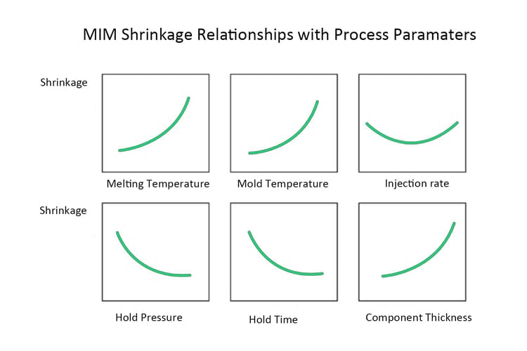
In metal injection molding process, we are well aware of the significant variation in shrinkage rates of molded parts. Therefore, maintaining a narrow tolerance range of ±0.3% for parts is quite challenging.
Most of the shrinkage variation in MIM arises from uneven feedstock density during the injection molding process. Hence, in practical production, we focus on the following parameters:
- Hold pressure
- Hold time
- Mold temperature
- Injection rate
- Uniformity of feedstock
If you have better solutions, please share them with us.
At BLUE, we top metal injection molding services. We support part weights from 0.2 g to 300 g, tolerances within ±0.3%, and densities up to 99% of theoretical. Our materials include stainless steel, low alloy steel, soft magnetic alloys, and titanium—serving industries such as automotive, medical, and electronics.
FAQ
1. What are the Difference between Metal Injection Molding vs Die Casting?
Metal injection molding is ideal for producing small, complex parts, while die casting is suitable for larger parts. The biggest difference between MIM and die casting lies in the raw materials.
MIM is the process of forming a final product by metal powder injection molding. Die casting is the process of filling a mold with molten metal to form a finished product.
2. What are the Difference between Metal Injection Molding vs Plastic Injection Molding?
Metal injection molding and plastic injection molding use different raw materials. The process of metal injection molding is more complicated and the cost is higher.
3. How Long Does Metal Injection Molding Take?
Metal injection molding takes about 24-36 hours, including debinding and sintering process.Die casting is the process of filling a mold with molten metal to form a finished product.


