


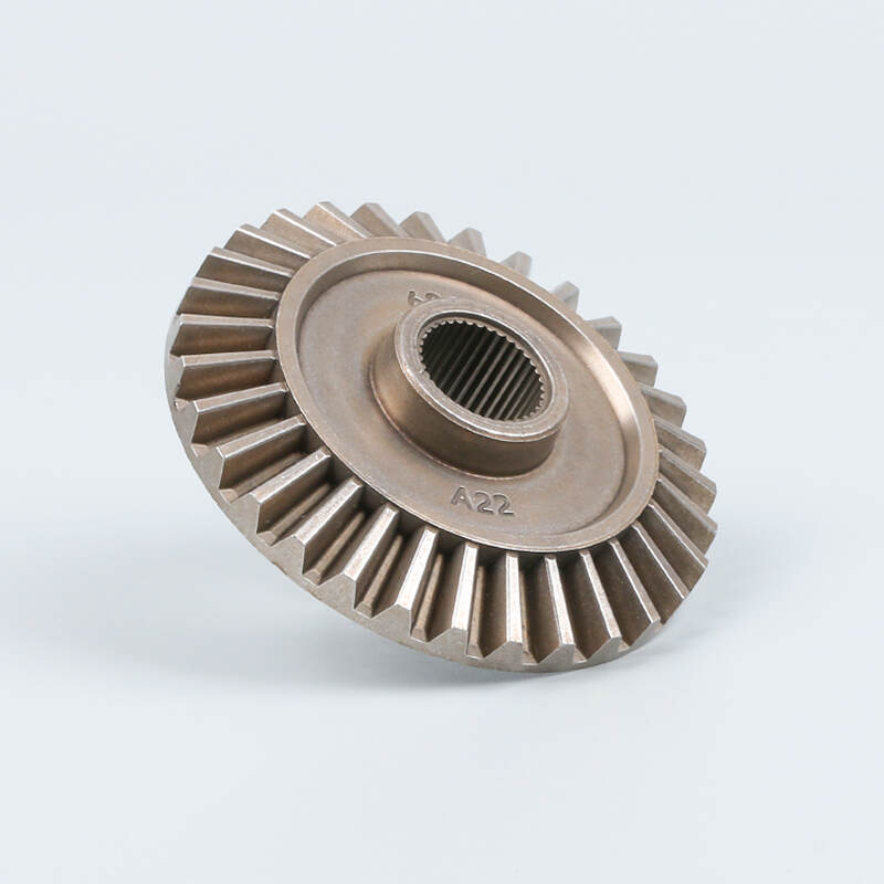
A bevel gear is a conical gear used to transmit rotational power between shafts that intersect, typically at 90 degrees.
The tapered shape of bevel gears, in contrast to spur gears, allows them to change torque: the larger the driven gear, the more output torque at a cost of speed, controlled by gear ratios. Bevel gears are commonly used to transmit power between intersecting shafts. With proper design, alignment, and lubrication, straight and spiral bevel gears can achieve high efficiency, typically in the range of approximately 95–98%.
Contents
Understanding Bevel Gears
Bevel Gear Cones
Bevel gears on which the imaginary cone is a locus of tooth contact, with their conical surfaces of pitch. The point of the intersection of the shafts is the apex of this cone (the cone center). This makes the gear teeth fit into each other properly to transmit power through controlled rolling and sliding contact.. This shape has a conical geometry, which enables the teeth to change in terms of thickness and profile. Usually slimmer at the end (narrow) and the other end (fatter), which dictates the distribution of strengths.
According to a study in MDPI, contact stress can be greatly minimized by optimizing the cone geometry, including changing the cone angle and making tooth modifications, thereby enhancing the tooth life at high speeds.
Bevel Gear Pair
A bevel gear system is in two parts: a smaller pinion engaging a larger gear. The shape of the two, particularly the angles of the pitch cones, should be shaped in a way that they roll on a common apex. This helps to maintain pure contact when the two roll.
The alignment of the pinion and gear should be accurate because any misalignment would translate into torque transmission, stress build-up, and may cause vibration. Simulation and finite-element modeling studies have demonstrated that a simple approach to relieving the tooth profile at the ends can significantly reduce both contact stress and bending stress despite alignment errors, leading to improved load distribution and more efficient and smooth meshing. This will improve efficiency and increase the service life of the gear set.
Working Mechanism of Bevel Gears
Bevel gears also pass on motion by engaging their teeth at converging angles, an effective method of passing power between intersecting shafts. In straight bevel gears, the teeth are also cut in straight lines on the surface of the cone, and they fit each other abruptly in a single point of contact. This sudden action may result in increased forces of noise and impact, especially at increased speeds.
Conversely, in spiral and hypoid bevel gears, the teeth are curved (in the spiral bevel gear, spiral-shaped; in the hypoid bevel gear, hyperbolic). These are curved teeth, and they come together: they touch at one end of the tooth as the gears turn. The step-by-step development of the force makes the process of transferring force less jerky, smoother, and more gentle in the reduction of vibration and noise.
Bevel gears are usually heat-treated to achieve accuracy and permanence, followed by the grinding of their teeth. This post-treatment grinding eliminates any distortions of the heat treatment to ensure the correct tooth geometry and avoids early wear throughout the lifecycle of the gears.
Efficiency of Bevel Gears
The design of bevel gears is highly sensitive to efficiency, as this directly influences the energy loss and thermal characteristics in a transmission. Experimental studies indicate that bevel and hypoid gears may reach efficiencies of 93.5 to 98% under load, speed, micro-geometry, axial offset, and condition of lubrication.
Factors that influence this efficiency include:
- Sliding friction losses: In spiral and hypoid bevel gears, the curved tooth profiles generate significant sliding during meshing. As a result, this increases friction and reduces efficiency.
- Micro-geometry and surface contact: Optimizing tooth surface topography (for example, through tooth-end relief or micro-geometry modifications) improves load distribution and reduces frictional losses.
- Lubrication: Appropriate lubrication plays a vital role in reducing contact losses. High-quality gear oils help to minimize sliding friction and thermal losses.
- Axial offset and alignment: Misalignment or axial offset increases sliding and lowers efficiency, whereas precise alignment improves performance.
- Trade-offs with noise and vibration (NVH): Higher efficiency designs may increase noise or vibration, so designers often balance efficiency against NVH targets.
Advanced design methods, such as optimization algorithms (e.g., PSOGSA), have been successfully used to fine-tune machining parameters and tooth geometries to push transmission efficiency above 98% in spiral bevel gears.
Types of Bevel Gears
Straight Bevel Gears
Straight bevel gears have straight teeth and simple geometry, which leads to low sliding during meshing and high transmission efficiency when properly aligned and lubricated. But these straight-cut teeth are actuated abruptly, and the entire width of the teeth produces high impact forces when meshing at high speed; hence, the cause of why they produce more noise when the operation is at high speed.
Their great efficiency and less complex geometry are suited to industrial machinery with moderate torque, where the speed is regulated, and vibration or noise is not so important
Spiral Bevel Gears
Spiral bevel gears have curved teeth that engage accessibly. This design minimizes noise, vibration, and shock loads. Studies prove that they are better in terms of their durability and easier operation than straight bevel gears.
Zerol Bevel Gears
Zero bevel gear is similar to spiral gears except that the teeth are curved with a zero spiral angle. They combine the smoother, quieter operation of spiral bevel gears with the consistent, predictable axial thrust of straight bevel gears.
Hypoid Bevel Gears
The hypoid bevel gears are special gears with distinctly different, offset axes, which makes them have a bigger pinion diameter, providing the tooth contact area and higher torque capability. They have curvy, spiraling teeth that wedge in slowly and minimize vibration and noise while maintaining loads.
Hypoid gears are used in car differentials to enhance the handling processes because the driveshaft is mounted at a lower position, reducing the center of gravity of the car. Non-parallel design, however, produces more sliding friction, thereby producing less efficiency and necessitating high-performance lubricants with extreme-pressure additives.
Miter Bevel Gears
Miter gears are a type of 1:1 ratio gears that are based on bevel gears but allow intersections between shafts at 90 degrees. They are applied in an aspect where an equivalent speed transmission is required. They are simple and reliable, making them appropriate to use in light industrial processes.
Manufacturing Processes for Bevel Gears
CNC Machining
Bevel gear teeth are shaped to micron-level accuracy with CNC machining and control pitch angles, tooth depth, and spiral curvature. The approach minimizes backlash, gives proper meshing, and increases gear life. Aerospace and automobile bevel gears are based on the use of CNC to obtain complex gears that are also efficient at high loads.
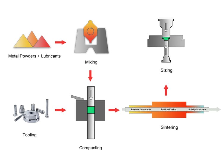
Powder Metallurgy
Powder metallurgy generates bevel gears by compressing metal powders into a die, which is then sintered to form a solid structure.
This process enables the manufacture of complex, small, or lightweight bevel gears with minimal material waste and is well suited for powder metal gear applications that operate under low to moderate torque.
Compared with traditional manufacturing methods, it provides consistent material properties and typically requires fewer post-processing operations
Gear Cutting
Gear cutting (hobbing or shaping) is a progressive procedure involving the removal of material to shape correct bevel gear teeth. The process is perfect with small batches and prototyping, which allows accurate tooth profiles. Distortions are usually eliminated by post-heat treatment grinding to maintain long-term guarantees of durability and good flow of power in the mechanical systems.
Face Hobbing
Face hobbing is a continuous generating method that forms bevel gear teeth through synchronized rotation of the cutter and the gear blank. This produces very precise tooth geometry and a straight finish to the surface. Face milling provides precise tooth geometry, while residual stress control and durability are achieved through subsequent heat treatment and finishing processes. It finds wide application in automotive and industrial bevel gear sets where precision is of great importance.
Face Milling
Face milling bevel gears entails the excision of the material using a rotating cutter along the cone of the gear. It gives the power to shape the tooth angles and provides smooth and accurate surfaces. It is not as fast as hobbing, but its use with large gears of marine or industrial use, where strength, accuracy, and longevity are the primary considerations, is appropriate.
Failure Modes of Bevel Gears
Fatigue and mechanical failures are common in bevel gears. Studies show three primary failure modes:
Pitting: Surface fatigue due to repeated stress cycles.
Tooth Interior Fatigue Fracture: Initiated internally from stress concentration.
Scuffing: Occurs under poor lubrication or high-speed sliding contact.
Advantages of Bevel Gears
Efficient Power Transmission
Bevel gears are very useful in diverting the torque in interlocking shafts (usually at right angles), with the least energy loss through their optimum tooth geometry. This is why they are perfect in systems where there is a lack of space, and power must be transmitted with minimal losses.
High Torque Capacity
Such types of gears as spiral and hypoid bevel gears can support very high load levels, as the tooth profiles are curved, which means that the load is divided into several teeth. Even sophisticated mathematical modeling demonstrates that the number of contact points on the tooth surface can be increased to lower the stress and greatly increase the load capacity.
Wide Range of Speed Ratios
Bevel gears can be used to adjust the quantity of gears and their geometry (pinion and larger gear), so that the range of speeds is flexible, enabling designers to trade off between torque and speed.
Compact, Space-Efficient Design
Bevel gearboxes are very small in shape, being cone-shaped, and therefore occupy less space when used in applications like vehicle differentials and industrial machinery.
Smooth and Quiet Operation
Spiral bevel gears, especially, offer this gradual tooth contact, and thus reduce vibration and noise, important in high-speed and precision applications.
High Mechanical Efficiency
Bevel gears with proper lubrication and alignment can be designed with very high efficiencies, and thus are of low-energy consumption in strenuous mechanical systems.
Limitations of Bevel Gears
Complex and Costly Manufacturing
The cone-shaped teeth are precise and involve CNC or advanced gear cutting that makes them expensive to produce. Such finishing operations, especially the gear grinding, require special tools and labor to obtain the appropriate topography of the surfaces.
Higher Noise in Straight Bevel Gears
Straight bevel gears make sudden contact since the teeth get in touch with each other in only one line. This sudden contact, especially at high speed, leads to higher vibration and noise than the curved-tooth type, such as spiral bevels.
Increased Axial and Radial Loading
Axial (thrust) and radial forces on bearings and shafts are caused by misalignment or bad assembly of bevel gears. These forces increase the rate of wear, and harder housings and bearing supports are required.
Demanding Lubrication Requirements
Hypoid and spiral bevel gears create large amounts of sliding between teeth, and therefore, they have a high level of friction. These gears demand special lubricants that are capable of withstanding intense pressure and heat in order to avoid scuffing and flank wear.
Reduced Efficiency in Hypoid Designs
Since hypoid gears slide over their tooth surfaces instead of rolling over them, they dissipate more energy to friction. This slipping action reduces mechanical efficiency in comparison with straight bevel gears.
Applications of Bevel Gears
Automotives
In vehicle differentials, bevel gears (particularly spiral or hypoid) enable the wheels to turn at varying frequencies, upon turning, to enhance handling and minimize tire wear. They also find their way in transmission systems and steering assemblies, where their angular geometry is used to convert and divide torque effectively.
Heavy Equipment
Bevel gears are used in construction and mining machinery (e.g., excavators, loaders, cranes), where they can be used to move extremely large loads and redirect the shaft direction. Their strength makes them very reliable in terms of transferring torques even in harsh conditions.
Aviation
Bevel gears have applications in aerospace in helicopter rotor drives, aircraft accessory gearboxes, and in the redirection of power at specific angles. They are required in their strength-to-weight ratio, which is critical in flight.
Industrial Plant Equipment
Bevel gears are used in the manufacturing plants in equipment such as conveyor systems, mills, and cooling tower fans. These gears reposition and multiply torque and possess great efficiency in small areas.
Marine Transmission
Bevel gears are applied in the propulsion and steering systems of ships and marine vessels. They are suited to the maritime powertrains because of their capability to manage high torque and their ability to perform within salty conditions.
Power Tools
In power tools, bevel gears play a crucial role in redirecting motion and torque between intersecting shafts, which is especially important in compact hand-held devices.
Electric Drills:
- Right-angle drills use a small bevel gear set inside the gearbox so that rotation from the motor shaft is turned 90° to drive the spindle.. This allows the drill bit to spin effectively while keeping the motor and handle aligned for ergonomic handling.
Angle Grinders
Angle Grinder gear functions as a bevel gear that transfers power across the 90-degree layout between the motor shaft and the cutting wheel. This design keeps the tool compact while delivering the torque needed for cutting and grinding.

Research and Automation
In robotics, bevel gears are used in custom gearboxes for precise joint motion and compact actuators. They are also critical in renewable energy systems (like wind turbines), where they control blade pitch or power transmission at changing angles.